
Can conductive polymer cables for power grids reduce insulation failure?
Conductive polymer cables can reduce certain pathways to insulation failure, but they do not replace the need for a sound insulation system. Their value lies in controlling local electric-field concentration, limiting the electrical consequences of small defects, and sometimes creating a measurable response to developing damage. Whether that translates into longer service life depends on where the conductive polymer sits in the cable design, how stable its conductivity remains, and whether the surrounding insulation, accessories, and installation conditions are compatible with it.
For power-grid cable systems, insulation failure rarely begins as a uniform breakdown across an entire wall thickness. It often starts at a local discontinuity: a protruding conductor strand, a contaminant particle, a void, a poorly bonded screen, a damaged joint interface, or a moisture-related defect. The local field rises far above the nominal design value, initiating partial discharge, electrical treeing, thermal degradation, or surface tracking. A conductive or semiconductive polymer layer can make the field distribution more uniform at selected interfaces. That is the main mechanism by which it can lower failure risk.
Where conductive polymers change the electrical problem
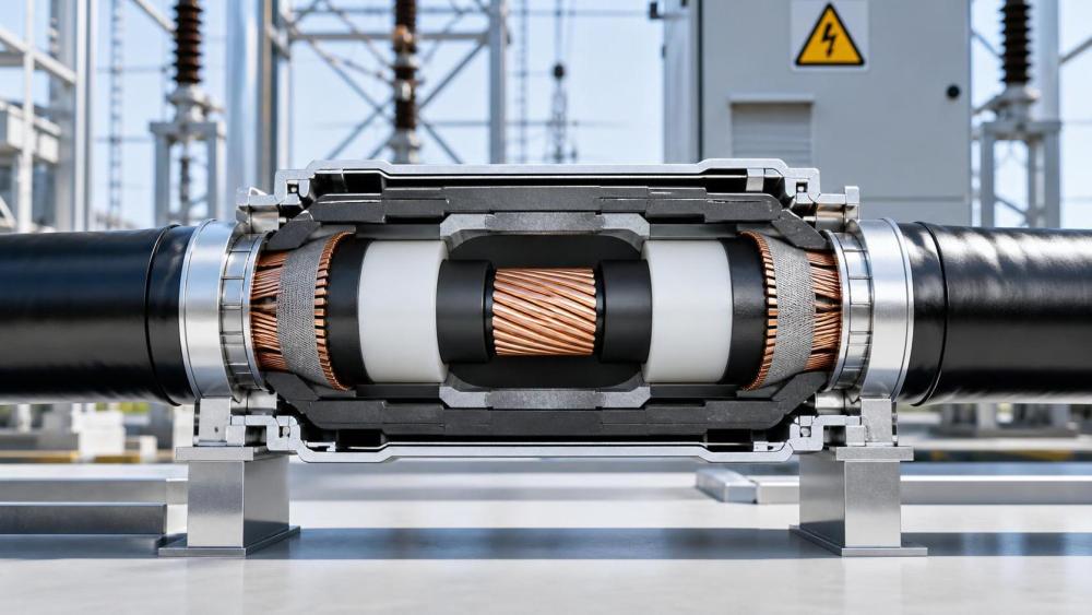
A conventional high-voltage cable already uses polymeric semiconductive screens around the conductor and insulation. These layers are not intended to carry bulk transmission current. Their purpose is to smooth the electric field, eliminate air gaps at the conductor boundary, and establish a controlled interface between metallic components and the insulation. Conductive polymer formulations extend this concept when applied as stress-control layers, field-grading materials, shielding elements, or functional layers integrated into cable accessories.
The relevant property is not simply “conductivity.” A material that is too conductive may create unacceptable leakage current, localized heating, or altered voltage distribution. A material that is too resistive may not sufficiently relax field stress where it is needed. Many stress-control applications rely on nonlinear resistivity: under elevated electric stress, the material conducts more strongly and redistributes the field; under normal stress, it remains comparatively resistive. This behavior can be useful near cable terminations, joints, and interfaces where geometry changes abruptly.
Conductive fillers such as carbon black, graphite, carbon nanotubes, metal-coated particles, or intrinsically conductive polymers can form a conductive network within a polymer matrix. The matrix determines mechanical flexibility, thermal response, processability, and environmental resistance. The filler network determines electrical behavior, but it is also sensitive to dispersion quality, filler loading, particle shape, and repeated thermal expansion. A specification based only on nominal volume resistivity can therefore conceal a material that behaves inconsistently after manufacture or service aging.
Failure modes that can be reduced, and those that cannot
Field grading is most relevant where insulation failure is driven by local electric stress. At a conductor screen interface, a smooth semiconductive layer reduces the effect of strand imprinting and surface irregularities. In a joint or termination, a conductive polymer stress-control component can reduce the peak field created by abrupt changes in insulation diameter, screen removal, or connection geometry. If the material maintains intimate contact, it can also reduce the chance that an air-filled interfacial gap becomes a partial-discharge site.
These benefits do not automatically address bulk insulation defects. A deep inclusion within cross-linked polyethylene, a chemically degraded insulation wall, severe water-treeing, or mechanical crushing damage may continue to progress even when the surrounding electric field is better controlled. Conductive layers also cannot correct poor conductor preparation, contaminated insulation extrusion, inadequate joint workmanship, or incorrect accessory dimensions. They reduce stress sensitivity; they do not make a cable indifferent to defects.
The distinction matters because several degradation mechanisms can present similar symptoms. A rising dielectric-loss signal may result from moisture ingress, thermal aging, contamination, or a changing conductive interface. Partial-discharge activity near a termination can stem from an internal void, a loose stress cone, surface contamination, or a damaged screen cut. Treating every abnormal signal as evidence that the conductive polymer has failed creates a misleading diagnosis. The defect location and the electrical pattern must be examined together.
The temperature question is often underestimated
Power cables are exposed to load cycles rather than a single steady temperature. The conductor, inner semiconductive screen, insulation, outer screen, sheath, and accessory components do not heat and cool identically. In a filled conductive polymer, this cycling can change the distance between conductive particles. Small dimensional changes may shift resistivity substantially when the formulation is near its percolation threshold, where a continuous conductive path is only just established.
This creates two opposing risks. A material whose resistance falls sharply at high temperature can produce excess leakage current or local heating under sustained load. A material whose resistance rises after thermal cycling may lose its ability to grade the field at the moment of highest electrical stress. Neither behavior can be inferred safely from a room-temperature data sheet.
Thermal conductivity deserves separate treatment. Adding conductive filler does not necessarily create a meaningful heat path through the cable. Electrical conductivity and thermal conductivity arise from different transport mechanisms and different filler networks. A formulation selected to equalize electrical stress may still have limited ability to remove heat from the conductor. Conversely, a thermally enhanced compound may not possess the controlled electrical response needed for field grading.
For direct-current systems, temperature gradients require even closer attention. Under DC voltage, charge injection and space-charge accumulation can reshape the internal field distribution over time. Conductivity that varies with temperature can move stress toward colder regions, interfaces, or insulation zones with different charge transport behavior. A cable design that appears well behaved under AC testing should not be assumed suitable for DC service without examining polarity reversals, load variation, thermal gradients, and long-duration voltage exposure.
Interfaces decide whether a promising material becomes a reliable cable
A conductive polymer layer performs through its interface with adjacent materials. Surface roughness, adhesion, shrinkage, and compatibility with the insulation compound all influence electrical behavior. A smooth, continuous semiconductive screen supports stable field control. A poorly dispersed compound can leave agglomerates, microvoids, or hard particles that create their own stress concentrations. A layer with poor adhesion can separate during cooling, bending, or thermal cycling, creating a gap exactly where the design intended to prevent one.
Processing history is therefore part of the electrical design. Extrusion temperature, residence time, shear history, screen thickness control, contamination control, and cooling profile can alter filler dispersion and surface finish. In factory-made cable, the interface may be co-extruded under tightly managed conditions. Field-installed joints and terminations introduce another set of variables: insulation removal quality, screen cut geometry, surface preparation, cleanliness, torque sequence, shrink or cold-applied component position, and moisture control.
A material with excellent laboratory properties can be undermined by a screen edge that is nicked, stepped, or left with conductive residue in the wrong location. At an accessory interface, even a small dimensional mismatch can change contact pressure and create a route for discharge. Inspection must consequently address geometry and workmanship as well as material identity.
What to compare beyond a conductivity value
When assessing conductive polymer cables for power grids, resistivity should be read as a curve rather than a single number. The useful question is how resistivity changes with electric field, temperature, frequency where relevant, and aging time. Directional behavior also matters for layered or filled materials: through-thickness and along-surface conduction may not be equivalent.
Dielectric loss, insulation resistance, breakdown strength, and partial-discharge inception behavior should also be interpreted in the context of cable construction. A lower measured loss is not automatically evidence of better insulation if the measurement arrangement has changed the conductive path. Likewise, a low partial-discharge reading on a short test specimen does not confirm that long cable lengths, joints, and terminations have the same interface quality.
Aging evidence should resemble the expected duty cycle
Useful qualification evidence couples electrical stress with the mechanisms expected in service. Thermal cycling alone can expose shrinkage and contact-pressure changes. Electrical aging alone can reveal charge transport or field-control limitations. Their combination is more revealing when the intended application sees variable loading. For buried cables, moisture exposure and sheath integrity are relevant because water pathways alter the insulation environment. For submarine or offshore export systems, bending history, radial water barriers, accessory sealing, and hydrostatic exposure can dominate the practical reliability outcome even when the conductive polymer itself is stable.
For flexible cable designs, repeated bending raises a separate concern: the conductive network can crack, rearrange, or become locally concentrated. The damage may not be visually obvious, yet it can alter resistance at an interface or create local heat generation. Rigid land-cable installations place greater emphasis on thermal expansion, soil thermal conditions, joint reliability, and fault-current exposure. The same compound should not be judged by an identical set of service assumptions across both environments.
Short-circuit duty also deserves attention. During a fault, conductor temperature and electromagnetic forces rise rapidly. A conductive layer that remains well behaved under normal load can experience temporary thermal excursions, differential expansion, or mechanical disturbance. Recovery after this event matters as much as its instantaneous behavior. Permanent resistivity drift or interface movement can leave the cable apparently intact while increasing its susceptibility to later insulation damage.
Condition monitoring is promising, but not automatic
A controlled conductive layer can support diagnostic functions when its resistance, impedance, or distributed electrical response changes predictably with temperature, strain, moisture, or damage. This could provide an additional observation channel beyond external sheath tests, temperature sensing, and conventional partial-discharge monitoring. The limitation is selectivity. A signal change may reflect ambient temperature, load variation, connector resistance, moisture, or material aging rather than a single defect mechanism.
Monitoring is credible when there is a stable baseline, temperature compensation, a defined measurement path, and a clear relationship between observed change and a physically plausible failure mode. Without those elements, a conductive polymer feature can generate more ambiguous data rather than earlier warning. In particular, connections to sensing or shielding layers must not compromise the cable's dielectric design, corrosion protection, or sealing arrangement.
Where the answer is strongest
Conductive polymers offer the clearest insulation-reliability benefit at engineered field-control locations: conductor screens, insulation screens, joints, terminations, stress-relief components, and specialized cable constructions where interface quality can be controlled. They are less persuasive as a broad claim that a cable will resist all forms of insulation aging. The material has to preserve a narrow balance among conductivity, nonlinear response, thermal stability, adhesion, mechanical flexibility, and chemical compatibility.
A credible design review follows the defect path from conductor geometry through each interface to the outer shield, then asks how the conductive polymer changes the local field and whether that change persists after processing, installation, load cycling, and aging. When that chain is supported by representative testing rather than isolated material values, conductive polymer technology can meaningfully reduce insulation-failure exposure.
Related News
- Computing Power Demand Adds Over 100 Billion kWh a Year as Experts Discuss Grid PlanningNov 04, 2026Prof. Marcus Chen
- Policy and Industry Demand Accelerate Solid-State Transformer CommercializationNov 03, 2026Prof. Marcus Chen
- What is driving demand in the smart microgrid controller market?Oct 12, 2026Prof. Marcus Chen
- What makes a smart grid project financially viable?Sep 03, 2026Prof. Marcus Chen